Hydraulic Fracturing Engineering and Software Solution, for Your Most Challenging Reservoirs.
StimPlan™ Version 7.20
Frac-to-Frac Stress Shadowing
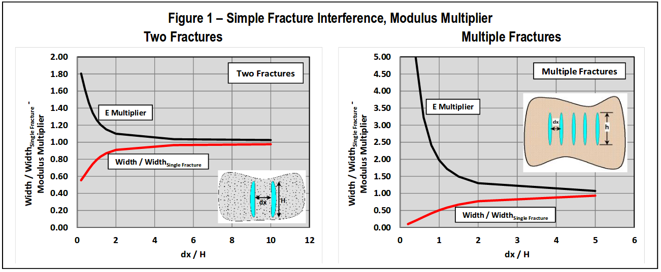
A major change for Version 7.20 is in the simulation of multiple, parallel fractures and how the mechanical interference (stress shadowing) between fractures is calculated. When this simulation feature was first added to StimPlan™ 3D, computer resources were such that it was not possible to run a time-step-by-time-step calculation for the stress perturbations created by the fractures, and the results of these perturbations on the multiple fractures. Thus, the simulations were done based on “Modulus Multiplier” correlations. That is, what is the effect on the pressure/width relationship for each individual fracture based on the presence of competing fractures on one or both sides. These correlations were then developed using many static finite element simulations.
Some simple examples of the “style” of these calculations is included in Fig. 1. For the simple case of two fractures, as the two fractures approach one another, the width of each fracture becomes exactly ½ the width of a single fracture (with the same internal net pressure). Thus, the Modulus Multiplier for each of the two fractures approaches 2. When the two fractures are separated by one fracture height, each fracture has approximately 80% of the width of a single fracture and the modulus multiplier is down to 1.2 – and there is relatively little fracture interference.
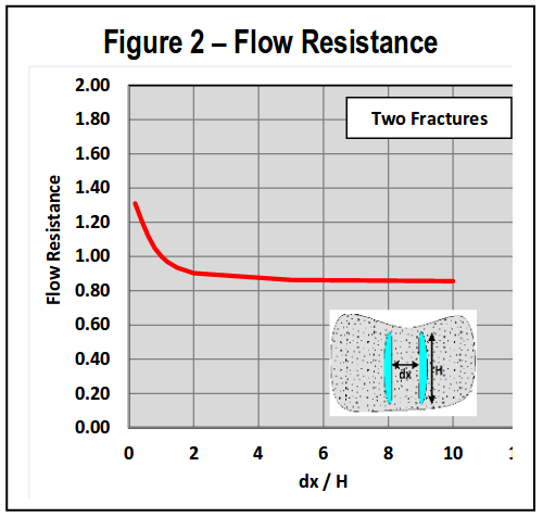
If this is recast as a flow resistance, the effect for two fractures is included in Fig. 2. This shows for a separation, dx/h, of one, flow resistance is “1”. That is, width is reduced by 20%; since pressure. drop down the fracture is related to width cubed, pressure drop (for a given rate & viscosity) increases by about a factor of 2 (1/0.83). However, rate is reduced by ½ since there are two fractures. Thus, total pressure drop down the length of each fracture is identical to the pressure distribution for a single fracture. Put another way, treating pressure at the well is identical for one, or two, fractures. Thus, fracture interference is near nil if fractures are separated by about one fracture height. Along with cases below, several checks were run against “ideal” cases such as these. Results were similar for both simu-lations.
Along with cases below, several checks were run against “ideal” cases such as these. Results were similar for both simulations.
When/How to Use
The default simulations for Version 7.20 still use the modulus multiplier correlations approach since run times are faster, and the answers are reasonably similar (see below) for many cases. The major cases (as known right now) when the more rigorous simulations should be used include:
- How – The “run time dialog” for running gridded model simulations has been modified as seen below.
- When–“Case 1” below prompted this development, and any case where the middle fractures show extreme height growth should use this new, more rigorous, simulation. It also might be used as a “check” on “simpler” multiple fracture simulations. However, as seen in Case 4 below, it is expected that for many (most?) simulations the simpler and faster simulation will be satisfactory.
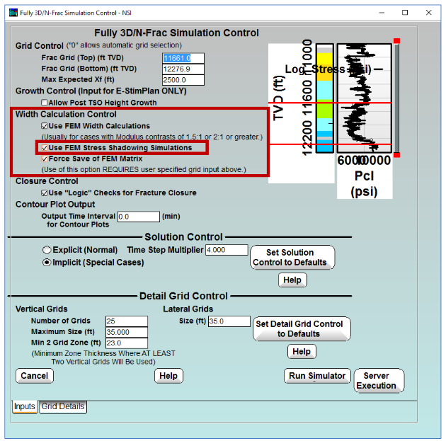
A double selection“Use FEM Width calculations” AND “Use FEM Stress Shadowing Simula-#tions” must be made to activate this FEM simulation.
Case 1–Height Growth
Fig.3 is the first case that came to light illustrating a problem with the correlations approach for fracture interference. The fractures initiate in Zone 1, and begin to grow laterally. Due to stress sha-dowing, the middle fractures are more difficult to propagate, and thus begin to preferentially grow in height. When the middle fractures encounter Zone 2, however, being above the outer fractures they should be able to preferentially grow length in Zone 2. However, the modulus multiplier is being applied over the entire height of the middle fractures, thus their width is still restricted even in Zone 2 – and these middle fractures just continue to grow more, and more height. Eventually, the outer fractures grow some height and penetrate into Zone 2. Being “outer” fractures, their modulus multiplier is lower (thus, for a given pressure they have more width), and they can penetrate out into Zone 2 without more height growth. It seems this is somewhat backward. That is, the inner fractures would grow height, penetrate Zone 2, and begin to grow laterally. After that lateral growth in Zone 2, the outer fractures would actually act to further confine the inner fractures to Zone 1.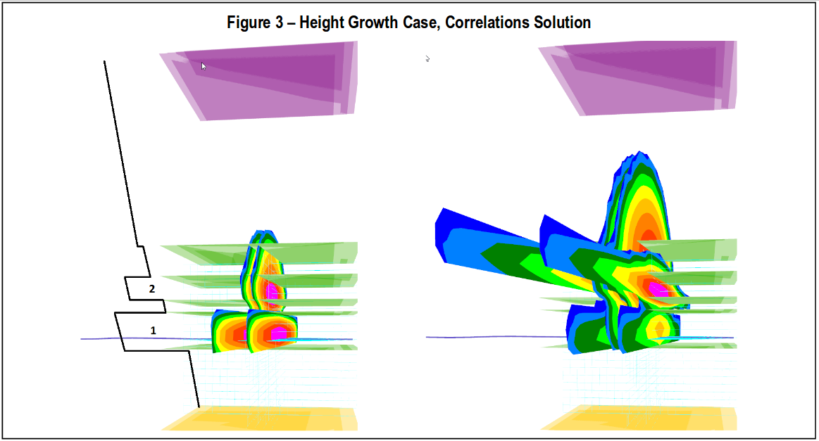
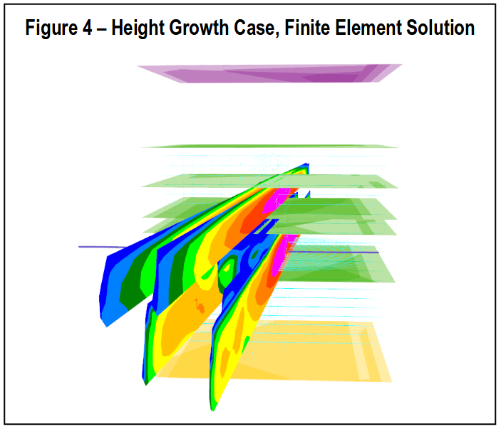
The results from the new finite element solution for this case is include in Fig.4. This seems to show a more “expected” behavior.
Case 2 – Hybrid Frac (Proppant Bridging)
The case illustrated here (Fig.5) is an Eagle Ford, hybrid fracture case. Both solutions show similar results as seen in the figure. When pumping fluid 4 fractures are created. However, on starting proppant the middle fracture bridges, resulting in only two primary fractures. While the late time result is similar, the behavior of the inner fractures is different.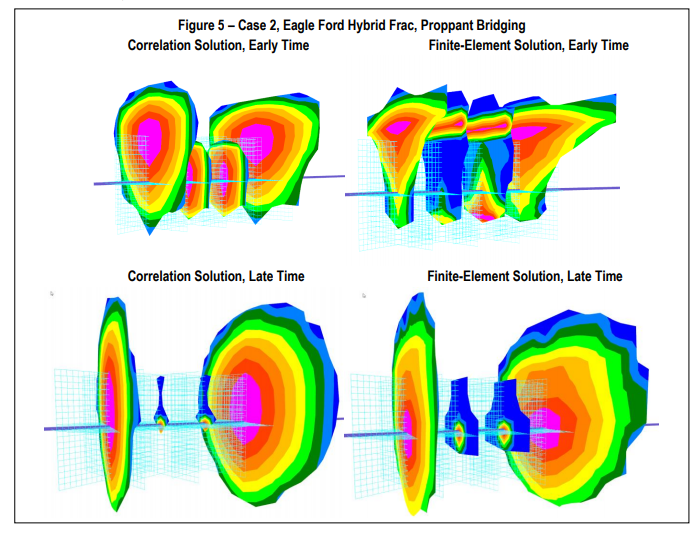
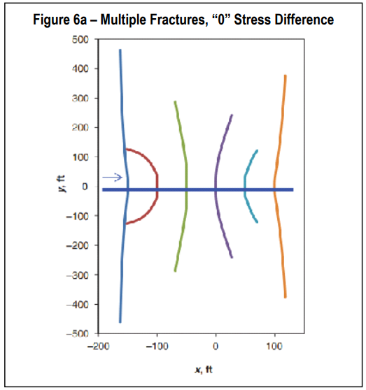
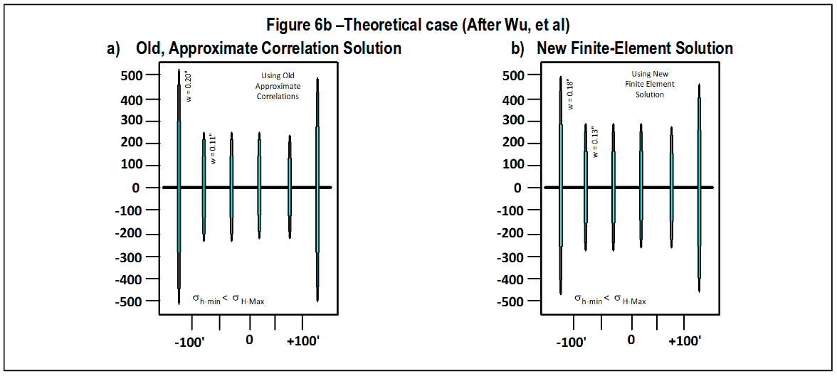
Case 3 – “Simple” Multiple, Confined Height Fractures
This case is taken from a publication by Wu, et al (“Simultaneous Multifracture Treat-ments: Fully Coupled Fluid Flow and Frac-ture Mechanics for Horizontal Wells,” Wu, Kan and Olson, Jon, SPE Journal, 2014) for multiple, simultaneous fractures under con-ditions of “0” stress difference. The results in Fig.6 show quite complex fracturing. Assum-ing some difference in the two horizontal stresses, the results might be more planar as simulated by StimPlan™. Obviously the planar simulation does not capture the complexities, but overall fracture lengths/widths agree with the published example, and are essentially identical for the two StimPlan™ approaches to multiple fracture interference.
a)_Old_Approximate_Correlation_Solution_New_Finite_Element_Solution.png)
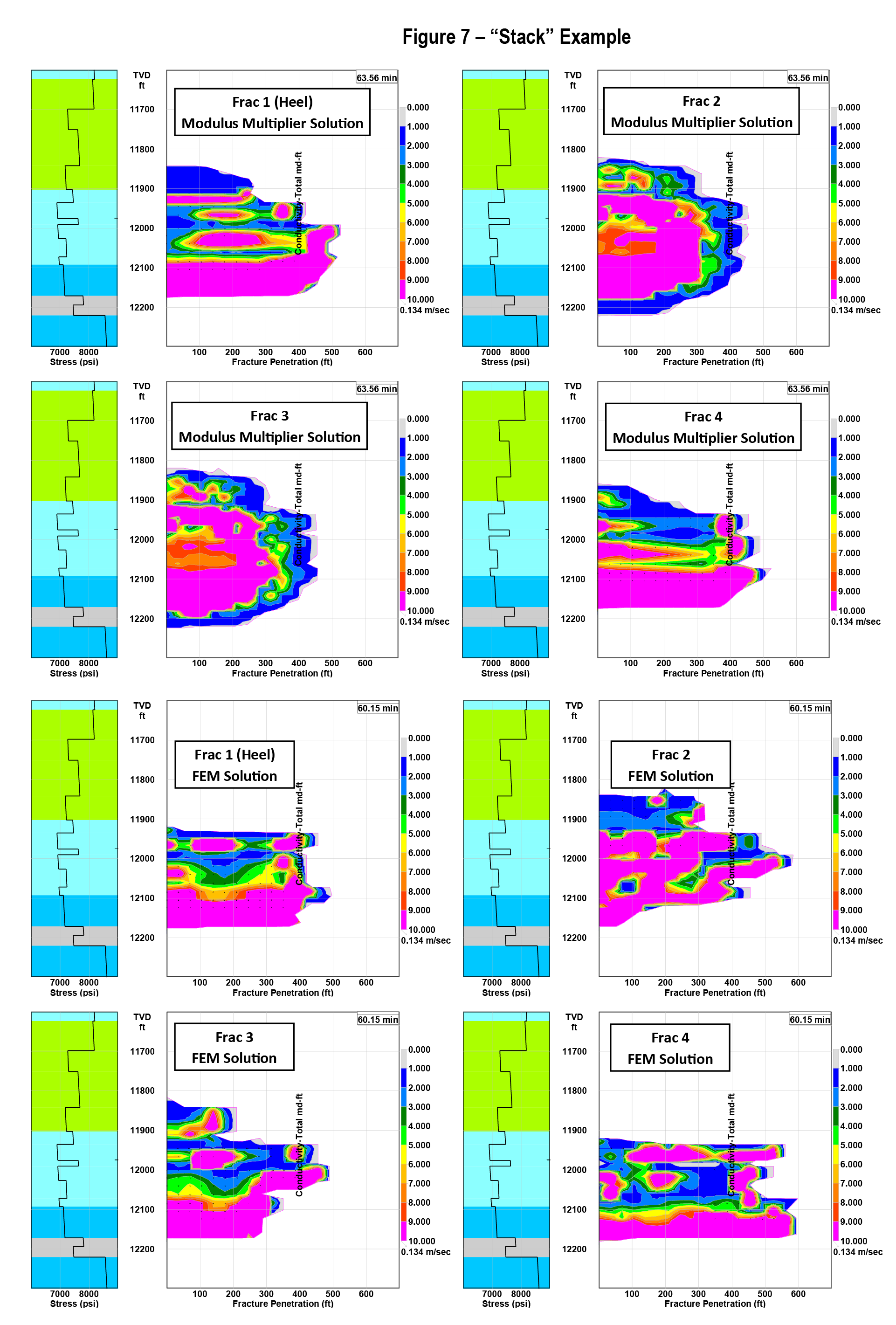
Case 4–O klahoma “Stack” Shale Oil Example
This is a current case of simulating water frac treatments in the Oklahoma “Stack” play. The results in Fig.7 do show differences between the “correlations” solution and the more rigorous FEM solution. However, the overall results for propped length, height, etc. are reasonably similar.