Hydraulic Fracturing Engineering and Software Solution, for Your Most Challenging Reservoirs.
NSI Technologies Frac Tips
Data Needs for Optimal Frac Design
The critical well in a field development needs to have a fracture design. What data is important to generate a good design? How would you go about generating the design? This Frac Tips is general overview of the required information, where it is obtained, and how it is utilized to generate treatment designs.
Information Needed
Reservoir InformationThe most important information to know or obtain is reservoir permeability. Permeability can be obtained from pressure build up tests, core measurements or nodal analysis. A pressure build up test can be used to determine reservoir pressure. Pressure can also be obtained from a direct measurement after perforating. Permeability and reservoir pressure can also be measured from the decline data after an injection (min-frac) test. A high permeability well might be designed with a tip screen out (TSO) where a low permeability well would need a long, lower conductivity fracture. For more information on whether a long, skinny fracture or a short, fat fracture is needed, please see the Frac Tips “Optimum Fracture Design.”
Reservoir porosity can be obtained from log measurements or core testing. Formation temperature is measured from logs. The production fluids (oil, gas, water) and their saturations can be calculated from logs and from core data.
The reservoir geology can also have a major effect on fracture design, primarily through drainage area. Treatment execution can be impacted by geologic features such as faults, unconformities, and fractures. Ignoring this information can have disastrous results. A visit with your friendly local geologist is always a good idea when designing a treatment in a new area!
Reservoir Fluid PropertiesThe reservoir wetting phase (oil or water wet) can be determined from core information or inferred from production in the same reservoir. Oil gravity, gas gravity and percentage of impurities ( CO2, N2, and H2S ) can be determined from laboratory measurement of fluid samples. The production yield (gas perbarrel or barrel per mcf) can be measured or estimated from other known reservoirs in the area.
Rock PropertiesA lithology log (usually Gamma Ray or SP) is critical to identify the formation layering (sand, silt, shale, etc.). The Young’s modulus of the rock can be determined from core laboratory measurements or inferred from measurement of compressional travel time. For more information, please see the Frac Tips ”Rock Mechanics For Fracturing”. Laser particle size or sieve analysis of core samples from the producing formation can yield data about formation size distribution and fines migration potential for “soft” formations.
Core can also be used to determine formation embedment and toughness (or apparent toughness). Apparent toughness controls the tip pressure required for fracture propagation. This is a complex variable that must be measured from field minifrac testing.
Wellbore and Production InformationA deviation survey is required for deviated wells. Offshore, the water depth is needed to calculate zone stresses. The existing casing size and drilling bit size need to be known so perforating charges can be chosen with the proper hole size/ penetration for the planned proppant size and concentrations. The perforating scheme for the well also depends on the wellbore deviation and fracture geometry. More information on perforating long intervals can be found in the Frac Tips “Perforating Long Intervals”. The work string needs to be sized for the planned stimulation treatment pump rates, and must be considered prior to choosing a fracturing fluid. The production string needs to be sized for the expected production rates as determined by a reservoir simulator, nodal, or company policy. The production line pressure or the suction pressure for the compressor and the associated temperature is required for an estimation of the production rates the reservoir will produce. Any other facilities data that could hinder potential production such as pipeline or separator size needs to be known.
Developing a Geomechanical Model
Stress ProfileA stress profile can be generated from historical data or by knowing the pressure profile for the zones and using the relationship in Equation 1, where σCL is the in situ stress or the fracture closure stress, OB is the weight of the overburden typically between about 0.85 and 1.1psi/foot-of-depth,ѵ is Poisson’s Ratio typically between 0.2 & 0.3, PRes is reservoir pressure, and T is any tectonic in-situ stress effects.
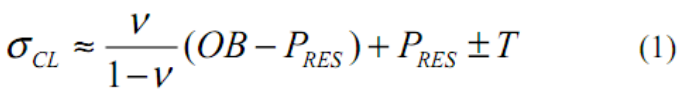
A dynamic value for ѵ can be determined from dipole sonic logs, and thus a stress log generated. Unfortunately, the log does not measure in-situ stress due to “T”, thus, log data MUST be calibrated with field measured in situ stresses.
Fluid Loss InformationLeak off or fluid loss is a function of formation permeability, reservoir temperature, and the viscosity (and wall building) characteristics of the fracturing fluid. A fluid loss profile can be generated from core testing, previous field experience, or estimated from published equations. Generally, a final value for fluid loss in a particular formation (with a particular fluid) must come from field minifrac testing.
There are many choices of fracturing fluids and proppants. A fracturing fluid should be chosen based on reservoir permeability as well as temperature and wettability of the formation. The fluid chosen should yield an efficiency of at least 10%. If less then a system with better fluid loss control should be selected.
The fluid should be tested with a viscometer using the chemicals from the field area and the local source water being used. Breaker schedules should be developed and tested in the laboratory, and confirmed in the field.
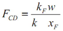
The proppant is selected based on the effective proppant stress, availability in the field, and price. A major consideration for proppant selection will be formation permeability and the “need” for fracture conductivity. This dependence on desired fracture conductivity, kFw, and formation permeability can be seen from dimensionless conductivity, FCD, where a desirable FCD is always at least 2 (> 2 may be desirable for lower permeability zones where transient flow is important).
Proppant stress can be calculated with Equation 2 where ∆ is incremental stress due to the propped fracture width. ∆ is usually small (200 to 400 psi) but can be significant in some cases such as TSO (tip screenout) treatments in a moderate permeability, “hard” rock. Pwf is bottom hole flowing pressure.
![]()
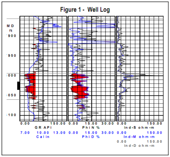
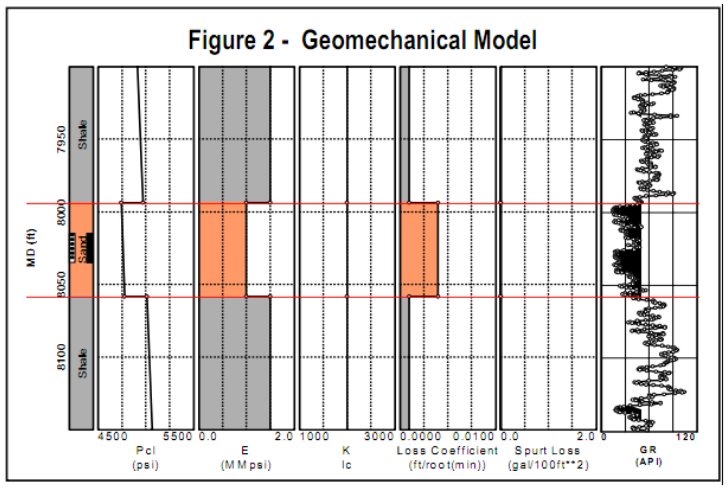
A rate accelerated well was drilled into a partially depleted low water drive gas reservoir. The reservoir is a large anticline structure and is fault bounded on one side. Reservoir properties can be found in Table 1. A core was taken in the first well and tested yielding a modulus of 1.0x10⁶ psi in the sand and 1.5x10⁶ psi in the shale. Poisson’s ratio in the sand was 0.25. The core showed the sand was not friable, so fines were not 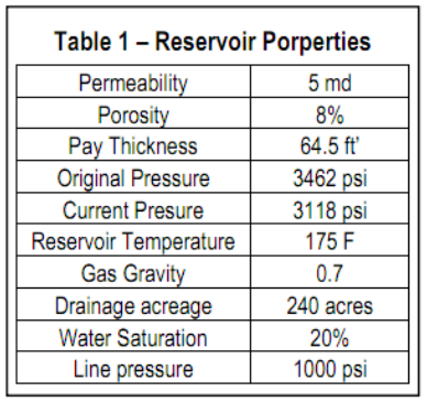 expected to be an issue. The well was located far from the fault, and was a non-deviated hole with 7” casing set to TD. It was logged with a triple combo log (see Fig. 1). A previous frac showed there were no tectonic effects, i.e., a “normal” closure stress. The sand stress was calculated to be 4,743 psi at the top of the pay zone with a fracture gradient of 0.59 psi/ft. The shale was calculated to have a closure stress of 4,886 psi at a depth of 7,856’ with a fracture gradient of 0.62 psi/ft. A 30 lb/1000 gal low guar gel system was chosen from the results of the previous frac yielding a leak off coefficient of 0.003 ft/√min, thus yielding an efficiency of 20% after a 7,000 gallon minifrac.
The proppant chosen for the job was an economical ceramic proppant. The price of the local sand and ceramic proppant were about the same, but the ceramic proppant yielded much higher conductivity numbers at the given stresses, and thus less proppant for the equivalent conductivity. This information was placed into StimPlan™ and a geomechanical model generated (see Figure 2).
The available information was placed into an analytical production model and determined the optimum fracture length was approximately 150’, with 1,500 md-ft of conductivity. This equates to an FCD = 2, or an optimal fracture length design. A proppant pump schedule can be designed to achieve these results.
ConclusionsTo generate an optimal fracture design requires data. Possibly the most important is an accurate permeability. Most of the information is readily available from sources within the company or can be obtained at reasonable expense. Previous fracture treatments in the same zone can yield valuable information for future treatments. Collecting, storing, and using this data can provide the greatest opportunity to successfully design and execute a fracture treatment in your reservoir.