Hydraulic Fracturing Engineering and Software Solution, for Your Most Challenging Reservoirs.
Frac Tips
Rock Mechanics for Fracturing
The objective of hydraulic fracturing is to design/execute a fracture treatment that achieves the desired fracture characteristics (length & conductivity) to maximize a wells production rate/reserves. To achieve this objective, there are several critical parameters to the process, and these fall into two distinct categories: a) parameters over which we have little control, but need to understand, and b) those that we control, but have lesser impact on the process. The first category includes fracture height, fluid loss coefficient, tip effects, and Young’s modulus. The second category includes pump rate and fluid viscosity.
The importance and interaction of these categories is best understood by reviewing fracture-modeling relations including both fracture geometry and material balance. For confined height fractures, for example, net pressure, fracture width, and shut-in pressure decline relations are shown in equation 1,
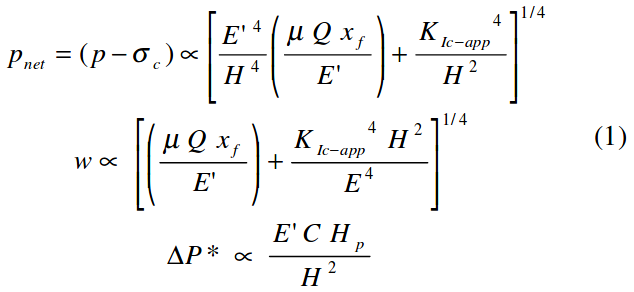
where ∆P* is the pressure decline parameter from pressure decline analysis, and is related to the rate of pressure decline.
This clearly shows that modulus is a very important, maybe critical, parameter to all phases of fracture behavior!As shown, net pressure is directly related to fracture height and nearly so to modulus. Also, note the limited role of viscosity, pump rate, and fracture length on net pressure. E is also a dominant parameter in determining fracture width. Finally, modulus affects the pressure decline behavior, and thus, the analysis of pressure decline data for the critical parameter, loss coefficient, “C”. Similarly, equation 2 shows PNet behavior for a radial fracture, again showing the importance of “E”.
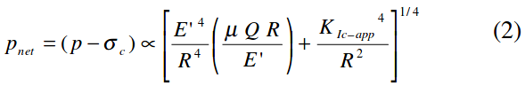
Interestingly, even for a Gertsma deKlerk model where fracture length is the critical parameter, net treating pressure and width are still nearly directly controlled by modulus.
These relations show that net treating pressure and fracture geometry are controlled by fracture height and modulus. Fracture height is generally controlled by insitu stresses and is difficult to directly measure. Fluid loss, “C”, is a complex function of the fracturing & reservoir fluids, formation relative permeability, fluid loss additivies, etc. Due to this, “C” must be measured by field tests – but analysis of these tests depends on modulus. Finally, tip effects, KIc-app, is poorly understood and impossible to measure directly. Thus, the ONLY variable subject to routine measurement from lab
tests is modulus. Certainly, definitive data for modulus is required before sensible use can be made of sophisticated 3-D fracture geometry models!
Plain Strain ModulusNote that the modulus needed in hydraulic fracturing and represented in equations 1 and 2 is the plain strain modulus, E’, where E' = E/(1-v2) shows the relationship between E’,
Youngs modulus, E, and Poisson’s Ratio, ν. Since Poisson’s ratio generally varies from 0.2 to 0.3 for hydrocarbon bearing rocks, it has little impact on the plain strain modulus.
Determination of Young’s Modulus -Hard RockTriaxial compression testing is used to measure Young’s modulus (E) and Poisson’s ratio (ν). In a conventional test, a cylindrical core sample having a 2 to 1 length to diameter ratio is loaded axially at a constant confining pressure. In addition to axial stress, the axial and lateral strains are monitored during the test and used to determine E and ν.
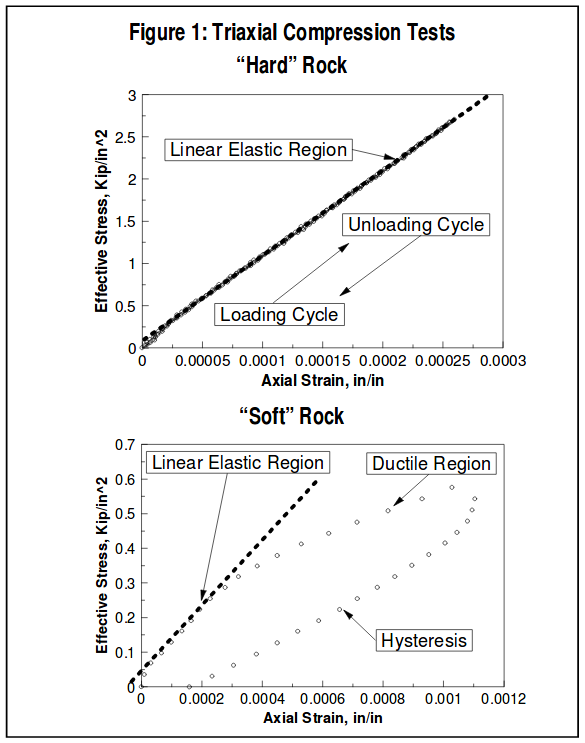
Figure 1 plots axial strain for a triaxial compression test of a carbonate core sample. Note that axial strain is linear throughout nearly the entire loading/unloading cycle. This sample was not taken to failure, and showed no evidence of destruction of the internal rock fabric. The slope of the linear portion of the axial strain curve represents the linear elastic constant, Young’s modulus. In this example, the Young’s modulus was determined to be 11.0 x 10⁶ psi. Poisson’s ratio is determined by a ratio of average lateral strain over average axial strain. For the sample in Figure 1 the Poisson’s ratio was determined to be 0.32 (though the actual lateral strain data is not included in the plot).
Determination of Young’s Modulus-Soft RockTriaxial compression testing can be used to measure Young’s modulus/Poisson’s ratio in soft and/or unconsolidated rock as well. In this testing, however, additional care must be taken to ensure sample integrity. Usually this means that core plugs must be cut with nitrogen and frozen until testing begins. As with conventional hard rock testing, a cylindrical core sample having a 2 to 1 length to diameter ratio is loaded axially at a constant confining pressure. In addition to the axial stress, the axial and lateral strains are monitored during the test and used to determine Young’s modulus/Poisson’s ratio. Figure 1 shows the axial strain for a triaxial compression test of an unconsolidated sand. As shown, the unconsolidated rock sample has a linear elastic region during the loading cycle of the compression test. However, at some point, the poorly cemented fabric of the sample begins to rearrange and deform. This ductile region, though not a catastrophic failure of the sample, does represent permanent deformation of the core plug. As a result, when the sample is unloaded, hysteresis is exhibited where the unloading cycle does not track the stress-strain behavior of the loading cycle.
Recognize that generally all core samples during destructive compression testing have ductile behavior. In hard rock, however, the ductile region occurs at or very near the confined compressive strength of the sample (failure point) and therefore is not always evident.
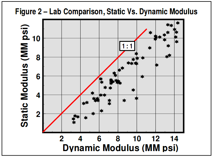
Static Vs. Dynamic Young’s ModulusThe modulus important to fracturing is the static linear elastic rock property, and MUST be measured by stress-strain testing as described above. Many in the industry have attempted to use the Young’s modulus determined from acoustic logs. The modulus determined in this manner represents a dynamic value, and nearly always differs greatly from static lab measurements. In fact, variations between static & dynamic modulus of a factor of two are common, and even larger variations have been reported. Also, note that dynamic modulus is always greater than static modulus, and since modulus directly controls PNet and fracture geometry, significant errors in these predictions result from utilizing dynamic modulus from logs. One set of published lab data comparing static/dynamic Young’s modulus is included in Figure 2.
Clearly this shows a trend, with static modulus always lower. However, there is significant “scatter” to the data for various rock types. In general, for a specific formation, it is best to use lab tests to determine a specific static/dynamic relation before sonic logs can be used quantitatively. Finally, note that while special (long spaced, di-pole, etc.) sonic logs
must be used to measure shear & compression velocity to calculate Poisson’s ration, a useable value for dynamic Young’s modulus can be found from a simple BHC Sonic (along with a density) log.
Further Application of Triaxial Compression DataIn addition to determining the basic elastic constants of Young’s modulus and Poisson’s ratio, triaxial compression testing can also be utilized to determine the confined compressive strength of the sample. If triaxial compression testing is performed at several confining pressures and coupled with unconfined compression and tensile test data, a representative failure envelope can be constructed and used to estimate formation failure.
ConclusionsYoung’s modulus is an extremely important parameter to the fracturing process, having nearly a direct relationship with the net treating pressure, fracture geometry, fracture width, and the determination of fluid loss from pressure decline data. Since Young’s modulus can be easily measured in the laboratory, it is recommended that in any area where hydraulic fracturing is used to complete and stimulate wells, core samples be taken and triaxial compression tests conducted to determine the elastic constants. Young’s modulus is the ONLY fracture design parameter that can be measured in advance, using laboratory testing!
Because net treating pressure is directly related to Young’s modulus, the need for accurate moduli in unconsolidated formations where frac-packing is the primary completion and well stimulation technique can’t be overstated. With this completion technique, the goal is to drive up net treating pressure (i.e. proportional to fracture width), and create wide, conductive fractures. The rate of net pressure rise, and thus fracture width are controlled by the magnitude of the modulus. Knowing the modulus prior to a fracpack can ensure the optimum completion and stimulation design, and that the required materials are available to achieve the objectives.