Hydraulic Fracturing Engineering and Software Solution, for Your Most Challenging Reservoirs.
NSI Technologies Frac Tips
Optimum Fracture Design
A fracture design has been placed in front of you. Is it the right answer for an optimum completion? How do you know? Is there too much, too little, or the correct amount of proppant? Is proppant strength correct for the expected closure pressure? Will the chosen fluid have enough viscosity to give the desired height or length? The goal of this newsletter is to highlight the characteristics of a properly designed fracture treatment. For this two terms need to be defined: Dimensionless Fracture Conductivity, and Folds of Increase.
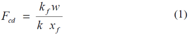
Dimensionless Fracture ConductivityDimensionless fracture conductivity (Fcd) is defined as fracture conductivity, kfw (md-ft), divided by reservoir permeability (k) multiplied by the fracture half-length, xf (ft) (Equation 1). It provides a means of optimizing the amount of conductivity in a fracture for varying permeability and fracture length.
It can be shown mathematically that for pseudoradial & pseudo-steady-state conditions, the optimum value for well productivity occurs at Fcd of about 2. For a given amount of proppant, two different types of fractures can be generated, a short fat fracture can be created with a high value of kfw, or a longer, narrow fracture can be created with a lower value of kfw. Fracpacks in high permeability zones (>1 md) deal with the short fat fractures with a high kfw, and in low permeability zones (<1 md), a long, lower conductivity fracture is desired.
For example, a partially depleted 50’ thick reservoir with 20 md and areal extent of 40 acres (re = 660’) has a 50’ frac half-length. To achieve Fcd = 2, a kfw of 2,000 md-ft is needed. If this same zone has a permeability of 100 md, the kfw required would be 10,000 md-ft to yield the same Fcd of 2.
What is Folds of Increase?Folds of Increase (FOI) is related to Productivity Index (PI) in a ratio of fractured versus natural completion. The FOI is calculated by determining the flow rates before and after a fracture stimulation treatment or FOI= Qf /Qnat. FOI can be calculated using Equation 2.
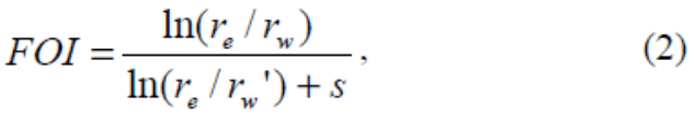
Where re is drainage radius, rw is wellbore radius, s is prefrac skin, and rw’ is the equivalent wellbore radius. Values for FOI can vary from 1, no stimulation, to values > 10 for very stimulated.
To calculate FOI, the Effective Wellbore Radius (rw’) must be defined (Prats, 1961, 1962). rw’ can be described as if a wellbore has been underreamed to an area equivalent to the area created from the frac as seen in Figure 1.
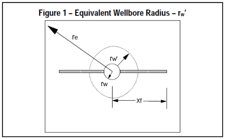
Several methods have been developed to calculate rw’. One method to calculate the “equivalent wellbore diameter” from Fcd is by using Figure 2 developed by Cinco-Ley. The relation described in Figure 2 is the heart of fracturing for all but the lowest permeability formations.
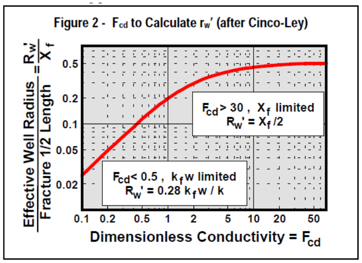
When Fcd is less than 0.5, rw’ = 0.28 x kfw/k, so the length doesn’t matter and the use of more or better proppant is required. Conversely, when Fcd is > 20, rw’ = xf/2, the fracture is acting like an infinite conductivity fracture and the use of better (stronger) proppants would be a waste of money.
Using the previous 20 md example, for Fcd= 2, rw’/xf equals 0.3. The xf of 50’ x 0.3 yields rw’ of 15’. FOI= ln(660/0.5)/ln(660/15) (assuming s=0) or a FOI of 1.90, almost doubling production.
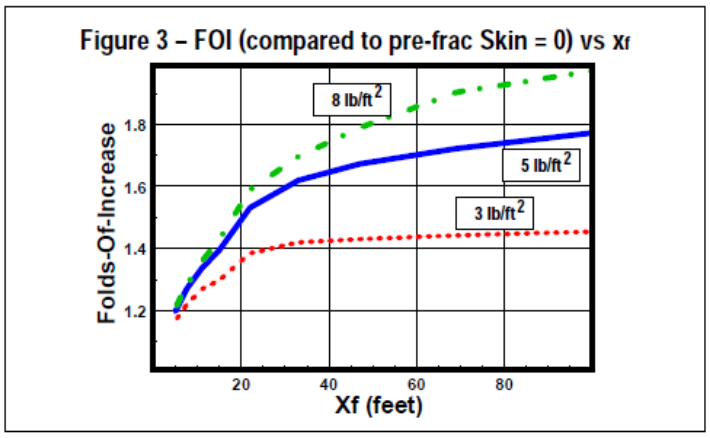
FOI Sensitivity for ReservoirsOne method for quick determination of the optimum fracture half-length and conductivity is running FOI sensitivity as seen in Figure 3. This does not give the best economic solution, but the best production solution. Note the FOI increases with length and conductivity. Thus, there is no single solution that produces optimum performance. But what is evident is a frac length
of 40-60 feet with 5-8 pounds/sqft (9,000-14,000 md-ft) appears to give the best results with FOI between 1.6 to 1.8.
 Effect of Different Proppants
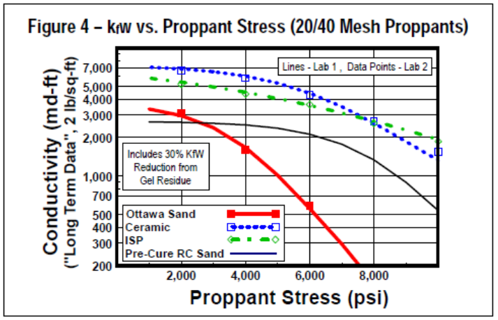
Conductivity varies with different proppants, and with proppant stress of the formation as seen in Figure 4. If Fcd calculated is very low, investigate increasing the concentration (pounds/sqft) or using higher strength proppant, which would increase the Fcd. Conversely, if Fcd is very high, a weaker (cheaper) proppant might be investigated to see the effect on FOI.
 How is Fcd Related to Production?
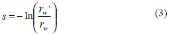
Postfrac production is affected by the skin near the wellbore. The more negative the skin, the lower the near-wellbore pressure drop, the higher the reservoir drawdown, and the higher the production rate. Conversely, with higher positive skin, the additional pressure drop near the wellbore reduces reservoir drawdown, and reduces rate. Fcd can be related directly to the-oretical skin ,that is the skin excluding wellbore jewelry. Theoretical skin can be calculated from Equation 3 by using the Effective Wellbore Radius. In the 20 md example above, skin would be -ln(15/0.5) or s = -3.4.
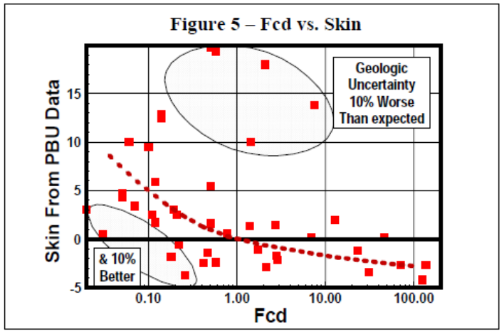
Post fracture Skins from pressure build-up tests have been plotted for various areas around the world in Figure 5. It can be seen as Fcd increases, skin decreases. If the Fcd is below 2, the fracture can be conductivity limited, meaning the reservoir permeability can deliver more production than the propped fracture can carry to the wellbore. Using FOI can optimize treatments to avoid this.
The discussion above was for wells with postfrac production dominated by pseudoradial flow behavior. In such cases, productivity can be predicted based on a skin, or an Equivalent Wellbore Radius, and the maximum productivity achievable with any proppant volume is for a combination of xf and propped width (kfw) giving Fcd about 2.
For low permeability zones (< 1/10’s of md) and longer fractures (xf of 100’s of feet or more), fracture transient flow (bilinear & linear flow) becomes important. For these cases, Fcd = 2 simply becomes a minimum design goal, and an optimum Fcd will be > 2 (sometimes >> 2). A goal of Fcd =10 is often used; however there is NO simple, single design value for such cases! The best procedure is to couple reservoir simulation and fracture modeling to determine proper design goals.
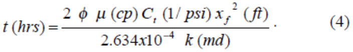
When will transient flow be important? An approximate answer comes from the definition of Dimensionless Time, tDxf. Fracture transient flow ends, and pseudo radial flow begins at (roughly) a dimensionless time of tDxf = 2. The time (hours) to the end of transient flow is given by Equation 4. If this is days/weeks, pseudoradial flow is dominant. If this is months/ years, then transient flow may be important, and the desired Fcd may be > 2 (or >> 2).
Another case requiring additional conductivity is when nondarcy flow becomes important. As with effects of fracture transient flow, there are no simple, single design goals. The additional kfw required should be determined with an appropriate reservoir simulator.
ConclusionsTwo of the most important factors for an optimum fracture design are Dimensionless Fracture Conductivity and Folds of Increase. The Fcd for an optimum fracture should be a minimum of 2. Whether permeability of your zone is 0.01 md and a long, low conductivity fracture is esired, or 100 md where a short wide fracture is needed, Fcd applies (optimum Fcd may vary from = 2 for moderate/high permeability formations, to > 2 for “tight” rock). FOI is a simple but very powerful design tool for all but the lowest of permeability zones.