NSI Technologies proudly presents www.fraceverything.com. Click here for your frac everything gear.
Hydraulic Fracturing Engineering and Software Solution, for Your Most Challenging Reservoirs.
Frac Tips
Perforating Thick Pay Zones
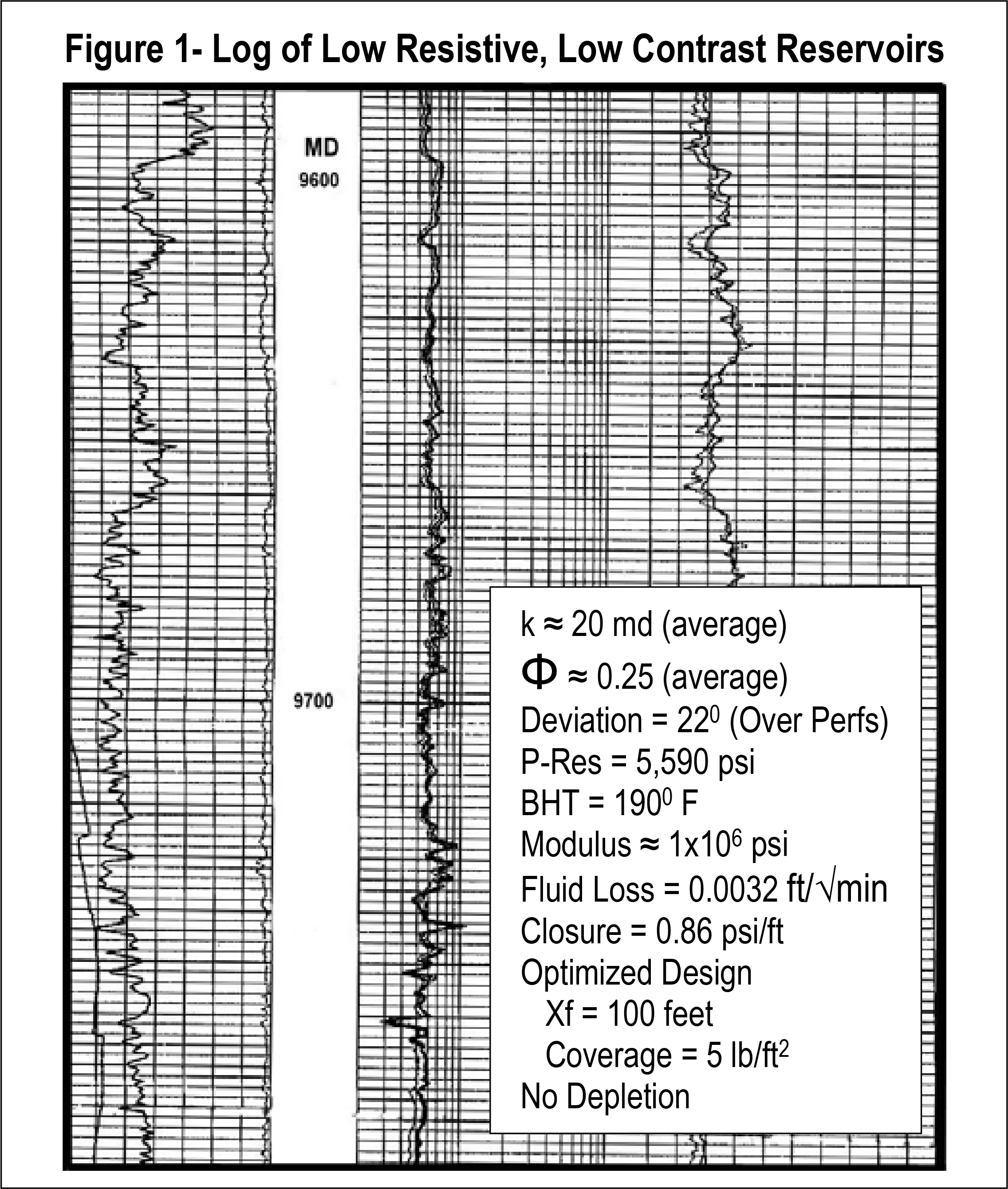
It has become common to complete Low Resistive, Low Contrast (LRLC) reservoirs as seen in Figure 1.These pay zones were often ignored in the past due to the difficulty in obtaining good wellbore-reservoir connection. However, fracturing (frac-pack) has made such reservoirs very profitable. These inter-bedded sand/shale sequences may have sands with permeability up to 100’s of millidarcies (md). This interbedded sand/shale sequence is what gives the reservoir the low resistive reading on the induction log and the volume of shale suppresses the gamma-ray log.
Once a thick, LRLC Rese rvoir has been identified, “How should I perforate it?” Conventional gravel-pack proce dures say, “perforate the entire pay”. For fracturing, this isn’t necessarily the best case. The formation could be perforated in the top, middle, bottom, or the entire pay. This article presents an evaluation of the optimum perforation strategy for long pay intervals completed with propped fracture stimulation.
Figure 1 displays the formation being evaluated, with the inset detailing reservoir properties. The fracturing fluid was chosen with enough viscosity to ensure good height growth to cover the entire reservoir (while still doing minimal damage to proppant pack conductivity). Several fracturing simulation runs were made to aid in discussing where to perforate the zone. The job necessary to cover the entire zone was 37.7 Mgallons of 35# cross-linked borate gel and 166,000 lb of 20/40 ceramic proppant. Pad volume was 10% of the entire job.
Perforate the Top and Bottom of Pay Cases
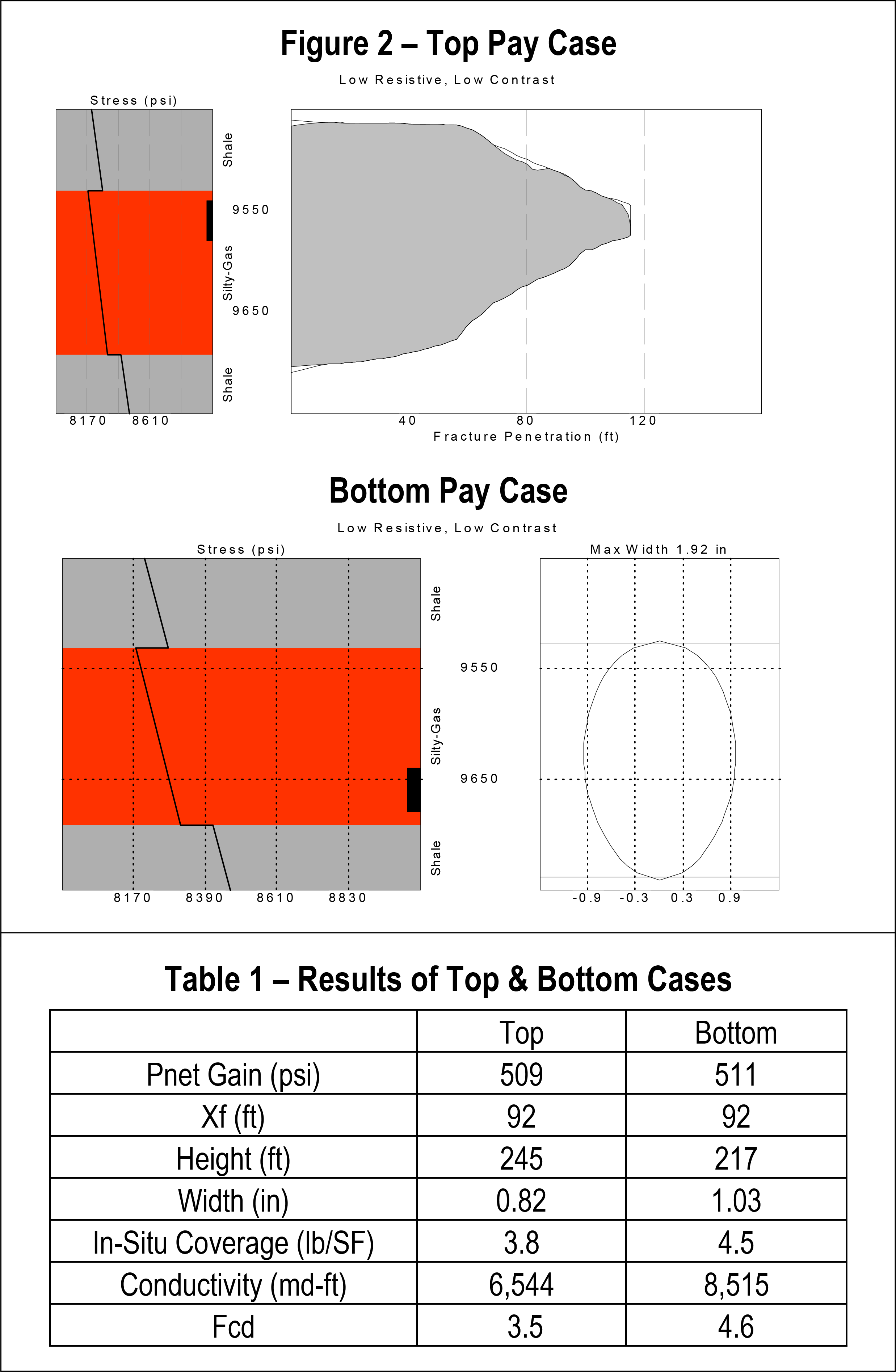
Two cases were considered where either the top (or the bottom) of the pay interval was perforated. The planned job was simulated separately for each case. Results can be seen in Table 1 and Figure 2. This shows a good, high conductivity fracture. However, despite assuming the overlying/underlying shale have slightly (but reasonable) higher closure stress, there is still significant height growth into the bounding beds. Thus, part of the fracture treatment is somewhat “wasted”.
Perforate Middle and Entire Pay Cases
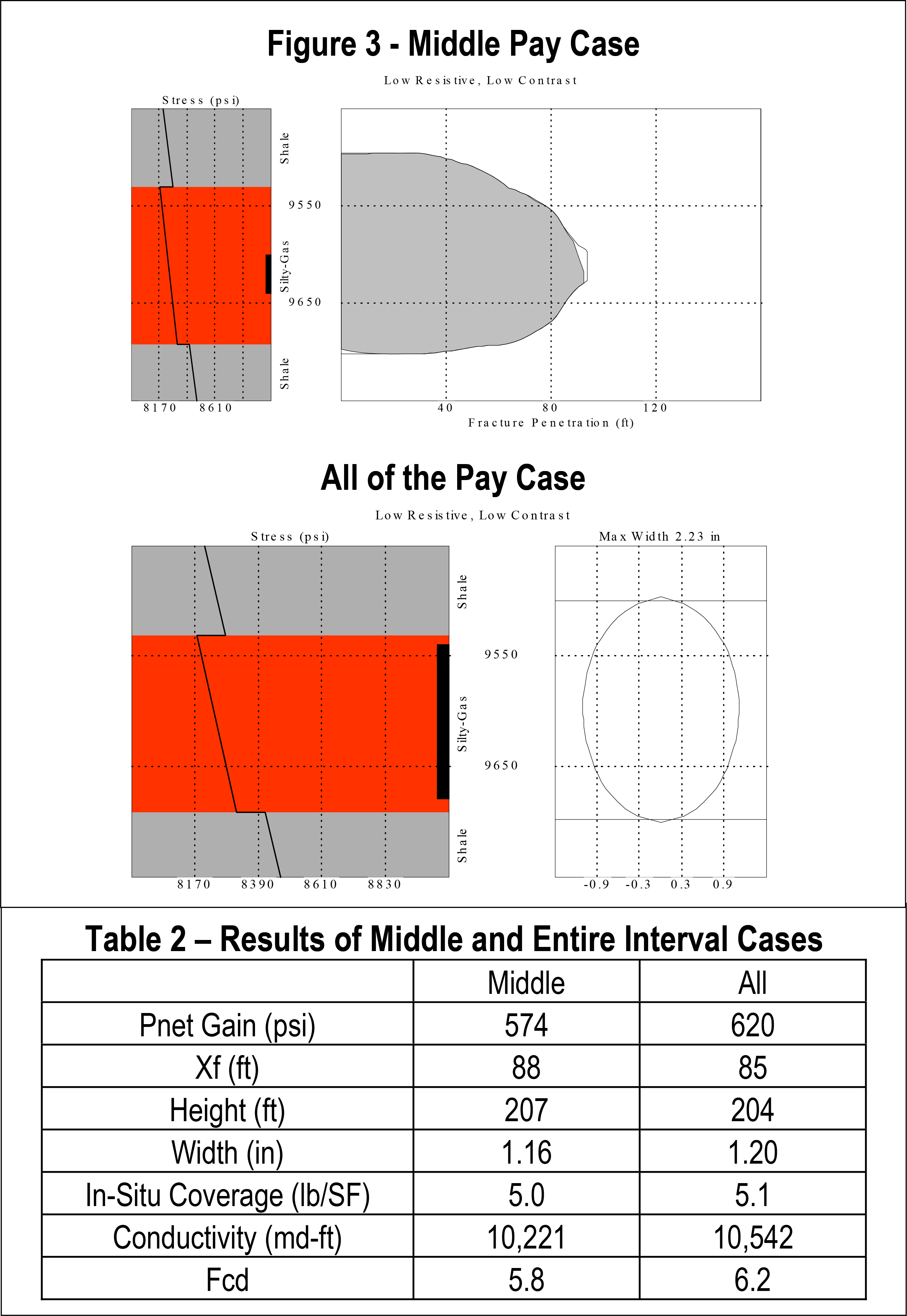
Two additional cases were considered where either the middle, or the entire pay zone was perforated. Again, the fracture treatment was simulated separately for each case. Results can be seen in Table 2 and Figure 3. With the perforation located in the middle and the entire pay zone, the propped fracture is concentrated in the pay and yields much better results. The design goal for proppant coverage is, in fact, achieved.
The Optimum Cases
Looking at the results, optimum cases are where either the entire pay, or the middle of the pay, is perforated. The entire pay case (optimistically) assumes the fracture initiates across the entire perforated interval simultaneously. This is probably not likely because the interval is very thick (140’ MD/122’ TVD) and the job was only pumped at 20 bpm. Fracture initiation for a virgin reservoir would be at the top (barring rock property differences) based on the inherent stress profile. Initiation at the top of the pay was the least beneficial case and would probably cause a poor annular pack. Net pressure behavior during a job could not distinguish where a fracture initiated, making diagnostics for any such problem difficult.
There are several other possibilities that could occur for the “whole pay perforated” case. The job may end prematurely because of a near wellbore event due to additional breakdowns along the perforations, holidays in the annular pack could form, or premature watering out with bottom water (if present) (if the fracture were to initiate over the
bottom of the perforations). The job ending prematurely will be caused by some mini-growths in height during the job. This is evident from the net pressure plot during the job. The net pressure drops quickly then rebounds and continues to climb parallel to the original slope. If the height grows upward and there is no pad to open the fracture, a near wellbore screenout is eminent. So it can be seen that the optimum results of perforating the entire pay are probably not obtainable, there fore it is not recommended to perforate in this manner for a thick reservoir to be fractured.
Best/Worst Cases For Fracturing
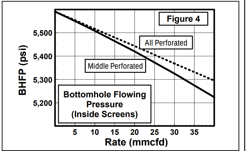
The best case for fracturing is to perforate in the middle of the pay. This is optimum because the fracture initiation is known and controlled, and the mini-growths in height will not effect the job because they will occur behind the pipe. Several simulation runs were made with a single-phase numerical gas simulator to determine the additional production pressure drop associated with the limited perforations. The pressure drop related to a partial perforation and annular pack is minimized (as seen in Figure 4) because the frac had grown from the top to bottom of the pay zone. The plot shows the BHFP inside the screen is only 70 psi more with the limited perforations case (than with the entire interval perforated) at 40 MMcfd. Note, that only 17 psi of the 70 psi represents additional pressure drop in the reservoir. Of course, rates from the well may vary significantly based on the size and type of tubing used.
The worst two cases were perforating the top or bottom of the pay because of the potential unconfined height growth. The bounding beds may have very little leakoff. The fracture was designed to enter the bounding beds to ensure good proppant coverage and then a tip event to occur. If there is near zero leakoff in the bounding beds, the fracture will continue to grow into the bounding beds as the leakoff in the pay zone decreases. This could lead to poor results as seen in the “Upper Case”. The fractured height is 38 feet more, and 36% less conductivity than the optimum fracturing case (Middle Case).
Conclusions
Perforating a limited amount in the middle of the reservoir is the optimal perforating scheme for long pay intervals when fracturing. This perforating plan works with all thick reservoirs (LRLC, high modulus, low modulus, consolidated or unconsolidated). The thick reservoirs will have similar stress profiles, fracture initiations and results as seen above provided there are no pressure depletion or rock property differences.